Hi Buddies,
Most of the time, we check the time on our phone or on store-bought wall clocks. But just imagine… what if we built our own digital clock? How cool would that be!
Today, let’s build a fully functional digital clock from scratch, step-by-step using the Buddy51 board.
Before we begin, this project uses some concepts from previous classes. If you haven’t watched those, please check them out first:
- Class 3 – How Single Digit 7-Segment Works
- RTC – Real Time Clock Concept
- Key Debounce Method
🔁 Quick Recap of Class 3
We saw how to use a lookup table to display digits 0–9 using 7-segment LEDs. When a button is pressed, the count increases and the value is sent to port P0 to display the digit.
1 2 3 4 5 6 7 8 9 10 11 12 13 14 15 16 17 18 19 20 21 22 23 24 25 26 27 | #include <8052.h> code unsigned char lookUpTable[10] = { 0xC0, 0xF9, 0xA4, 0xB0, 0x99, 0x92, 0x82, 0xF8, 0x80, 0x90 }; void delay() { int i, j; for (i = 0; i < 100; i++) for (j = 0; j < 1275; j++); } void main() { unsigned char count = 0; while (1) { if (P1_0 == 0) { delay(); // Debounce count++; if (count > 9) count = 0; P0 = lookUpTable[count]; } } } |
🛠️ Circuit Design for Full Clock
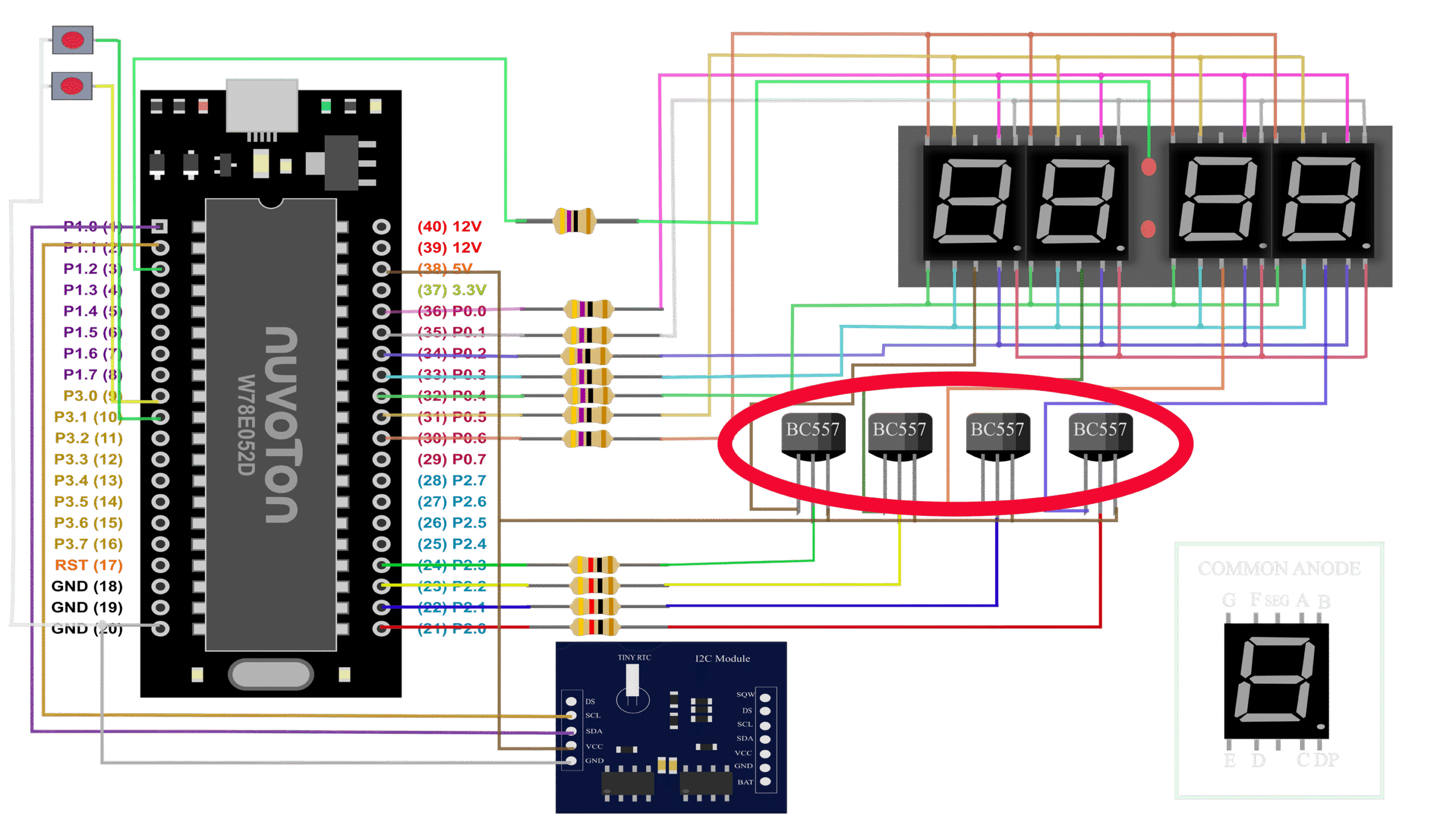
💡 Display Logic
To display each digit, we activate one transistor at a time and send corresponding data from the buffer. For example:
1 2 3 4 5 6 7 8 9 10 11 12 13 14 15 16 17 18 19 20 21 22 23 24 25 26 27 28 29 | code unsigned char lookUpTable[10] = { 0xC0, 0xF9, 0xA4, 0xB0, 0x99, 0x92, 0x82, 0xF8, 0x80, 0x90 }; U8 segmentBuff[4]; U8 disPos = 0; void main() { segmentBuff[0] = lookUpTable[1]; segmentBuff[1] = lookUpTable[2]; segmentBuff[2] = lookUpTable[3]; segmentBuff[3] = lookUpTable[4]; while (1) { P0 = segmentBuff[disPos]; P2_0 = (disPos != 0); P2_1 = (disPos != 1); P2_2 = (disPos != 2); P2_3 = (disPos != 3); disPos++; if (disPos > 3) disPos = 0; DelayXms(4); } } |
Why 4ms delay? Because human eyes need at least 60 frames per second to see smooth display. Since we have 4 digits, 60 × 4 = 240 cycles per second, which is approx 1/240 = ~4ms.
🕒 Adding RTC for Real-Time Clock
Now we integrate RTC. We read the time every second and update the display buffer accordingly.
We use a delay of 4ms, and a counter of 250 to make up 1 second (250 × 4ms = 1s).
1 2 3 | segmentBuff[2] = lookUpTable[minute / 10]; segmentBuff[3] = lookUpTable[minute % 10]; |
For example, if minute = 35:
- 35 / 10 = 3 (integer division)
- 35 % 10 = 5 (remainder)
The same is done for hours.
⏱️ Time Adjustment with Keys
Using the debounce logic we learned earlier, we increase hour and minute on key press, and update RTC.
✅ Final Code Without Interrupt
1 2 3 4 5 6 7 8 9 10 11 12 13 14 15 16 17 18 19 20 21 22 23 24 25 26 27 28 29 30 31 32 33 34 35 36 37 38 39 40 41 42 43 44 45 46 47 48 49 50 51 52 53 54 | #include <8051.h> #include "../library/Delay/Delay.h" #include "../library/DS1307/DS1307.h" code unsigned char lookUpTable[10] = { 0xC0, 0xF9, 0xA4, 0xB0, 0x99, 0x92, 0x82, 0xF8, 0x80, 0x90 }; U8 segmentBuff[4]; U8 disPos = 0; void main() { U8 count = 0; RTC_Init(); while (1) { if (!count) { RTC_Read(); segmentBuff[0] = lookUpTable[hour / 10]; segmentBuff[1] = lookUpTable[hour % 10]; segmentBuff[2] = lookUpTable[minute / 10]; segmentBuff[3] = lookUpTable[minute % 10]; count = 250; } count--; P0 = segmentBuff[disPos]; P2_0 = (disPos != 0); P2_1 = (disPos != 1); P2_2 = (disPos != 2); P2_3 = (disPos != 3); disPos++; if (disPos > 3) disPos = 0; DelayMs(4); if (P2_4 == 0) { DelayMs(1); hour++; if (hour > 23) hour = 0; RTC_Write(); } if (P2_5 == 0) { DelayMs(1); minute++; if (minute > 59) minute = 0; RTC_Write(); } } } |
🎉 What’s Next?
This version is simple and works fine for basic clocks, but the display may flicker or become less responsive when adding more logic. In future classes, we’ll explore how to handle these better using timer interrupts and multitasking techniques.
Stay tuned for the next lesson and subscribe to our full embedded project series. Let’s build together!
Leave Your Reply
You must be logged in to post a comment.