Hi buddies!!
In our previous class, we built a 7-segment display counter using an 8051 microcontroller. In this tutorial, let’s see how to display the same counter output on an LCD display.
📺 How Does an LCD Work?
An LCD consists of three major parts:
- Backlight – A small LED that provides light behind the display.
- Liquid Crystals – These crystals align when voltage is applied, allowing them to either block or twist light.
- Polarizer – A special filter that controls light visibility. When crystals twist the light, it passes through and appears blank. If light is blocked, the characters are visible.
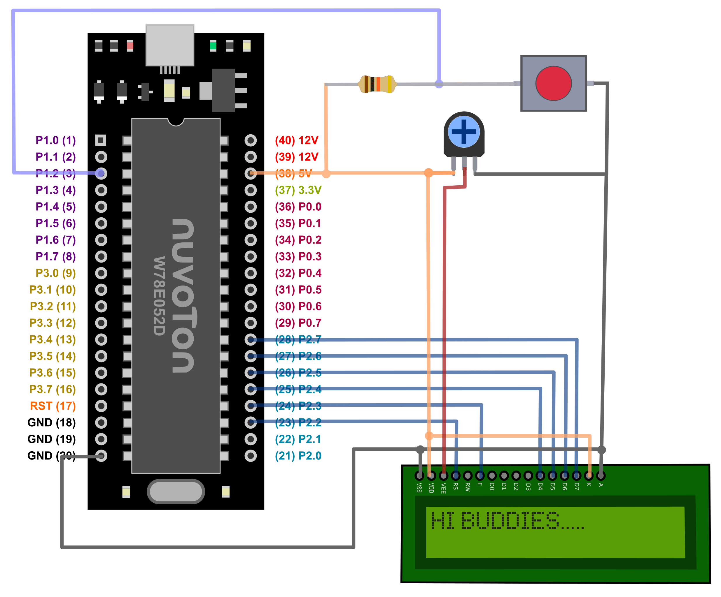
🔌 LCD Pin Details (16 Pins)
- Pin 1 & 2: Power supply (Vss, Vdd)
- Pin 3: Contrast adjust (via potentiometer)
- Pins 4–6: Control Pins (RS, RW, E)
- Pins 7–14: Data Pins (D0 to D7)
- Pin 15 & 16: Backlight (LED+ and LED–)
We’ll operate the LCD in 4-bit mode to save microcontroller I/O pins.
📘 8-bit vs 4-bit Mode
- 8-bit mode: Sends 8 bits (1 byte) at a time – uses all 8 data lines.
- 4-bit mode: Sends data in two nibbles (4 bits at a time) – uses only 4 data lines. Ideal when I/O ports are limited.
Control Pins Usage:
- RS (Register Select):
0for command,1for data - RW (Read/Write):
0for write,1for read (mostly we use write) - Enable (E): LCD latches data on rising edge (0 to 1 transition)
⏱ LCD Timing & Write Mode
Normally, LCD takes around 40µs to process a command or data. For special commands like clear, it might take up to 2ms.
Since timings are predictable, we usually keep RW tied to 0 (write mode) and use delays instead of reading LCD status.
⚙️ Hardware Setup
- LCD used in 4-bit mode
- RW pin connected to GND (always in write mode)
- Current-limiting resistors used for backlight
- Data lines D4–D7 connected to MCU (P0 or any suitable port)
🛠 LCD Functions Overview
You’ll need these 3 basic functions in your code:
- LCD_Init() – Initializes the LCD (Display ON, Cursor ON, 4-bit mode)
- LCD_Command() – Sends commands to LCD (clear, cursor control, etc.)
- LCD_Data() – Sends ASCII characters to be displayed
Internally, both LCD_Command() and lcd_data() work similarly, but the RS pin decides whether it’s a command or data.
1 2 3 4 5 6 7 8 9 10 11 12 13 14 15 16 17 18 19 20 21 22 23 24 25 26 27 28 29 30 | #include <8052.h> #include "../library/LCD4/LCD4.h" #include "../library/Delay/Delay.h" void main(void) { u8 key; unsigned char count = 0; char buffer[5]; // Enough to store up to 3 digits + null terminator LCD_Init(); // Initialize LCD LCD_Puts("HI BUDDIES!"); // Greet message DelayXms(1000); // Wait a second LCD_Command(LCD_CLEAR); // Clear LCD LCD_Puts("COUNT:"); // Display label while (1) { if(!P1_2){ DelayXms(10) while(!P1_2) DelayXms(10); count++; if (count < 99) count = 0; // Keep it 2-digit max LCD_Goto(2, 0); // Go to 2nd row, 0th col sprintf(buffer, "%02d", count); // Format count as 2-digit LCD_Puts(buffer); // Display counter } } } |
💡 Program Explanation
We’re reusing our old counter logic with small changes:
- Declare a buffer array
- Initialize LCD using
LCD_Init() - On button press, increment the counter
- Clear the display using
LCD_Command(LCD_CLEAR) - Convert the counter value to ASCII using
sprintf() - Set cursor position with
LCD_Goto() - Display value using
LCD_Puts()
Once uploaded to Buddy51 Mini board, press the button to see the counter increment from 0 to 9 on the LCD!
📺 Output
- Button press → count increments
- Value displayed on the LCD
- Clears and refreshes on each increment
❓ Have Doubts?
If you have any questions about LCD interfacing, 4-bit mode timing, or code setup, feel free to ask in the comments!
Stay tuned, and thanks for reading!
– Team BuddyKit 🚀
Leave Your Reply
You must be logged in to post a comment.